|
|
|


3D Drawing from engineering plans
 Other News
Subscribe to newsletter
Other News
Subscribe to newsletter
| 24 Mar 2019 |

Last time we looked at the easiest way to get started in 3D. If you followed along, you’ll now have a basic layout. This time we will be creating a window from a low-quality 2D engineering drawing, starting in 3D. There are easier ways of creating windows in BricsCAD BIM. We will talk about them later in this series.
Commands covered:
- BOX
- OFFSET
- FILLET/CHAMFER
- MANIPULATE
- 3DROTATE
- SCALE
- PARAMETRIZE
- EXTRUDE options
- View style
Making the frame
I’ve been given the plans for the windows. Unfortunately, it seems that the plans have been extremely poorly photocopied. This means tracing isn’t an option but that shouldn’t be a problem with BricsCAD.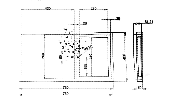
We’ve all seen rough markup like this before. You’ll be amazed how quickly you can reproduce this in 3D.
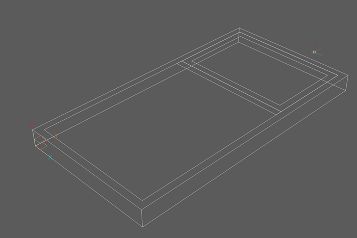
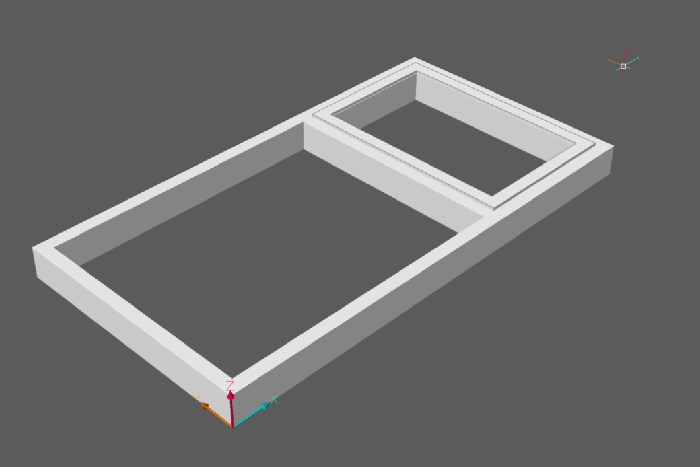
I began by using the box tool, then drew along the surface of the box to mark out my window panes and extruded.
To do this:
- Start by accessing the BOX tool (found in the Solids section of the Model tab on the Ribbon). To keep things tidy, my insertion was 0, 0, 0.
- Using the DYN boxes enter the width and length dimensions as specified on the drawing above. So far so easy.
- Then set the height (z-axis) in the same way.
- After that, use the OFFSET command to offset the edges of the box and draw the dimensions (as you normally would in 2D, but on the surface of the box, not the 0 plane of the z-axis). Tip: If you have problems drawing the the surface of the box check that DUCS is turned on.3d drawing
This gave me the following results:
- Use the Properties Panel or the View tab in the Ribbon to change the View Style to Shaded.
- To create the recess for the window, simply hover over the polygon until the boundary turns green. Select Extrude from the Quad and drag through.
- Then repeated the action to pull out the frame of the window’s “door” slightly.
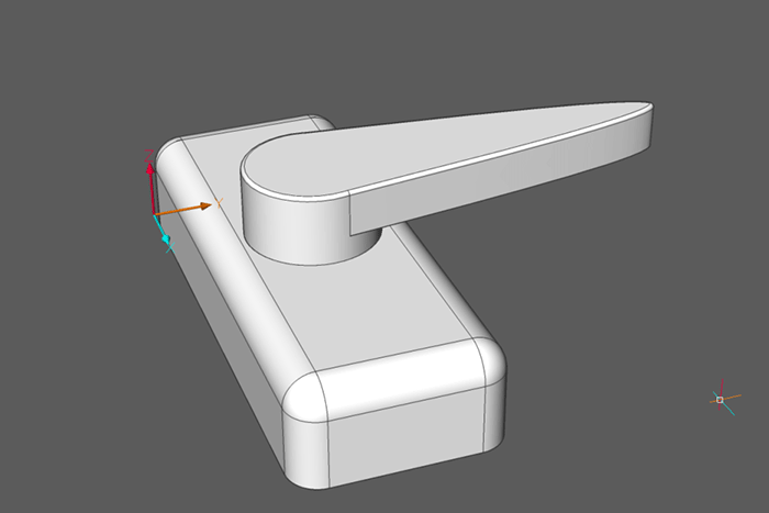
The handle
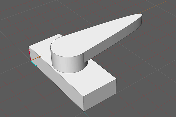
To make the handle, I started with the box and cylinder primitive shapes, then extruded the spline.To do this:
- Draw a box.
- Next, draw a cylinder in the center of the top surface of the rectangular box. Input the measurements according to the 2D plans.
- Then created the handle shape with a Spline.
- Finally, extruded the shape. 3d drawing
Tip: The TIPS interface allows you to change how the shape is extruded hit Ctrl to change between the options.

This resulted in:
Fillets
It looks OK, but it was missing the fillets. I added these to create a more polished finish. In 3D, chamfers and fillets work almost exactly like they do in 2D.To do this:
- First access the DMFILLET command, found in the Direct Modeling section of the Modeling tab on the Ribbon.
- Select the edges then enter the radius value. Tip: Use 2D Wireframe, View Mode, as it makes it easier to see every edge of a solid.
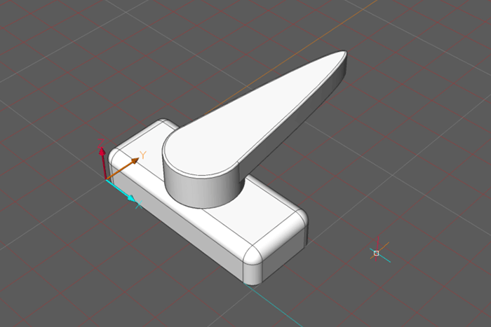
Now we’ve made it in 3D we can see that there is a bit of a problem: The handle is too big for the base. No sweat.
I fixed this by selecting the solid and using SCALE. I scaled it down to 0.7. You can see it now fits perfectly.
I used MANIPULATE (but you can also use MOVE) to move the completed handle into its position on the frame.
Details and tweaking
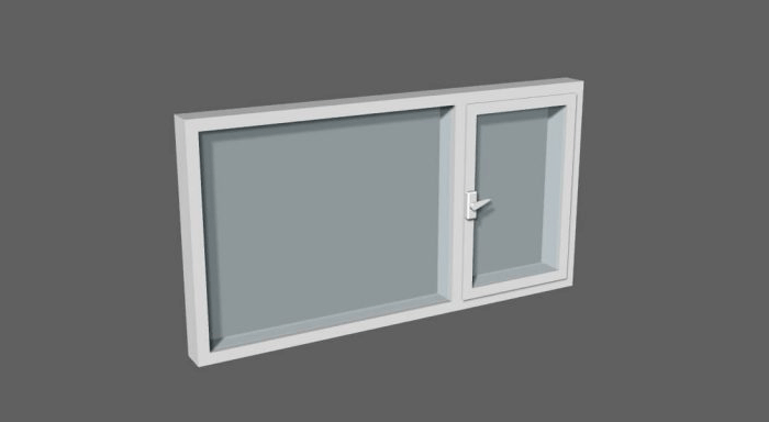
I made the window panes using Extrude and selected the create mode. This prevented the solids fusing automatically.
To differentiate the glass from the frame I used the color drop-down menu in the Properties panel to change the color from ByLayer to blue.
Finally, I used 3DROTATE – along the x-axis – 90°. 3D Rotate works exactly the same as 2D rotate, apart from the fact that you can rotate around a given axis.
Variations
At this stage I was pretty happy with my model, but I wanted to be able to use it in a range of sizes. To do this without remodeling again I used Parametrize.To do this:
- Enter PARAMETRIZE.
- Select the object(s) to Prarametrize.
- Open up the Mechanical Browser, you’ll see all your constraints!
- Edit them in the Properties panel.
Animating the Parametric constraints on the window to create a range of different sizes.
- Tip: If you’re not sure what parameter controls what, you can animate them. Just right-click on the parameter and hit animate. You can read more about constraints and parameters.
- If an object is over constrained it will be displayed in the Mechanical Browser colored red.
- Fix constraints will prevent you from rotating an object.
- Now save your model as we’ll be using it later.
Don’t have BricsCAD yet?
Easy to try, easy to buy, easy to own. That’s BricsCAD. Try all of our products, for free for 30 days at www.bricsys.com. Freedom of choice, plus perpetual (permanent) product licenses that work with all languages, in all places. You’ll love what we’ve built for you with BricsCAD.Written by Rose Barfield
#BricsCAD #CAD #BIM #BIM4DWG #Bricsys #HexagonPPM