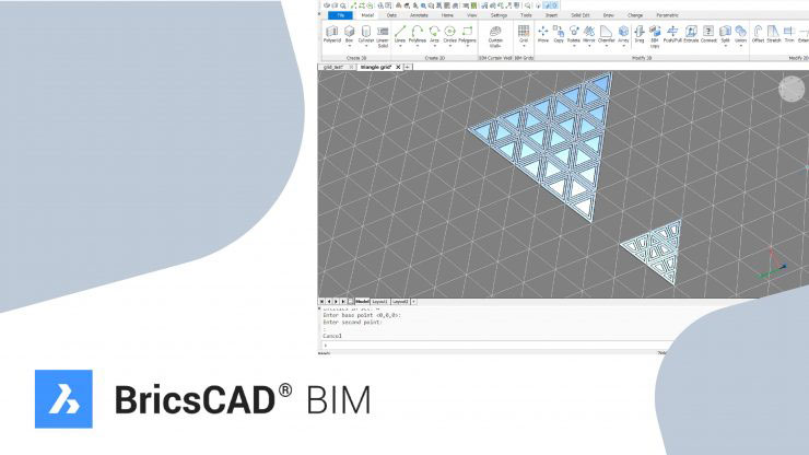
Grids in BricsCAD BIM
 Other News
 Subscribe to newsletter
| 19 Jan 2019 |
In this post we explore ways of dividing complex shapes into usable grids by showing you the all-new, BricsCAD grid system.
There isn’t really a set of tools specific to grids in BricsCAD. That’s because anything can be used as a grid! You already know how to design grids, if you already know how to use BricsCAD’s 2D toolset. If you don’t yet know how to, why not check out our tutorials?
The basics
There is a grid tool that can be used in rectangular and polar variants. Access it from the Quad, the Ribbon, the drop-down menu or the command line. Then simply set the values. If Dynamic Dimensions (DYN) are switched on, you can type these values into the blue boxes.
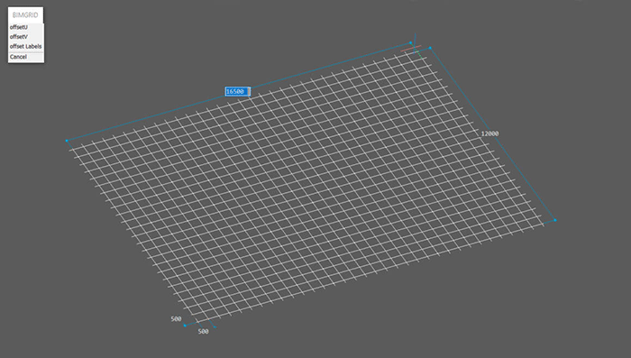
A basic grid shape
Once your grid is created, you can enter Block edit mode, either double click the grid or use the BEDIT command. Once in Block Edit mode, you can transform your grid to adapt to any layout.
Use the NUMBER command to automatically assign numbers, letters (upper and lower case) or roman numerals (upper and lower case).
If you add any lines, use the BIMCLASSIFY to convert them to grid axes (found in the “other” section). Then use the NUMBER command as you normally would.
When you’ve finished simply exit Block Edit Mode BCLOSE/-BEDIT and save.

top left, large grid labels, bottom left smaller grid labels, right, the properties panel with the label scale location highlighted
The labels can be turned on and off or edited for size in the properties panel, alongside the more familiar options such as line weight, unit type, etc.
Once created grids are invaluable for creating complex designs.
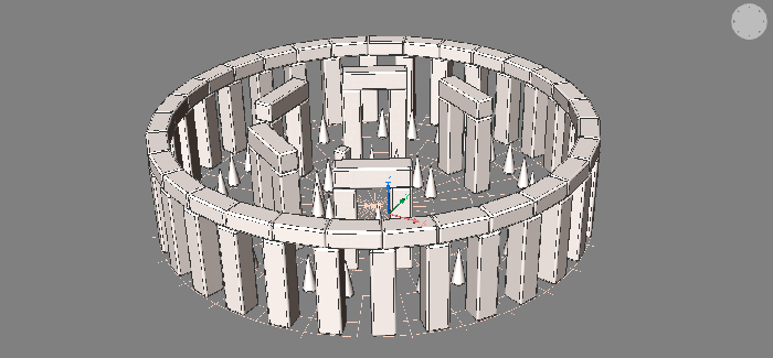
I used a highly modified grid to help me to create this Bricshenge CAD model.
Thinking outside the boxes
It doesn’t just stop at squares and circles! Why not try something more exotic?
As i am a massive triangle fan (I can’t be the only one to have a favourite shape?), I created my own 3-way grid. The best part: it was created as a block so I can reuse this grid over and over again!
To make the grid I created an array of lines at 60° and mirrored.
To get the perfect spacing between the vertical access I used the snap to draw two straight lines and selected them. Nearest distance came into its own here and showed me how far apart the lines needed to be spaced. I then applied this spacing to the array. Simple!
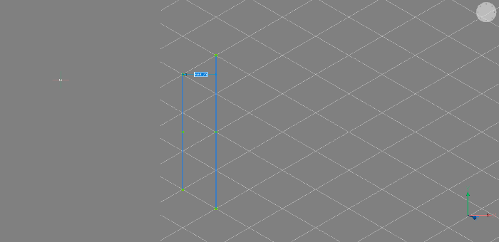
Nearest Distance is a really useful tool when measuring complicated geometric patterns.
I then used TRIM to tidy up the drawing.
Once this was completed, I launched the BIMCLASSIFY command and converted all lines to grid axes and then repeated the command to convert the axes into a Grid and checked the Convert to block and classify the block reference box.
I then opened BEDIT mode and launched the NUMBER command to relabel all axes. Because of the large variety of labeling options, I was able to have one set of lines with numbers, one with letters and one with roman numerals.
Non-Euclidean grids
Grids don’t just stop at Euclidean geometry. You can use the BIMPANELIZE command to create non-euclidian grids too! Simply select the surface you want, launch the PANELIZE command and set the numbers of U and V axis dividers. It works just like the curtain wall BIMCURTAINWALL command.
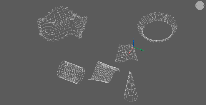
non-euclidean grids are possible with BricsCAD
I’ve made my grid, now what?
If an object is placed at an intersection of a grid, propagate will automatically detect the other locations where this object can be replicated along the grid. Watch here as they create and edit a radial grid and then use PROPAGATE to quickly place a large number of columns along grid points.
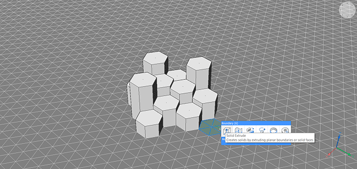
drag out sections of a grid to create details
Hovering over a grid works much the same as hovering over any set of lines, the fill area is automatically detected and can be adapted and extruded as desired. You can even use the BIMWINDOWCREATE command to automatically create windows, as shown in the banner image.
#BricsCAD #CAD #BIM #BIM4DWG #Bricsys #HexagonPPM #Grids #2D #3D #Drafting


